The first part seemed to have gone well. Perhaps it wouldn’t be wrong to say it went at least 80% as well as I could have hoped.
By far the biggest problem I now faced was time. A lot of the equipment I ordered, such as the lathe, didn’t arrive until part way through the exam. Overall I had just a week to finish everything (out of an allowed 3 weeks) and we were now getting into the final few days.
What this really meant, as we shall see, is that mistakes – which are bound to happen – cannot be satisfactorily corrected. In the first year practical exam I made plenty of mistakes, but I had enough time to correct them or rework that entire part.
Unfortunately even with hindsight, there wasn’t much I could have done. Circumstances beyond my control had dictated my timescale.
The reality now was that when I made a mistake, the primary concern would not be reworking that piece but rather damage control. In an exam such as this means that you have to accept that you will lose marks, but just take actions that limit as best as you can the number of marks that you will lose.
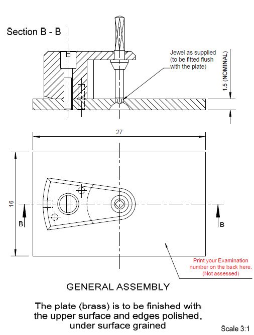
This article will show the process I went through to make the plate.
I started by printing off the copy of the technical drawing I had made earlier. I set the size to be 1:1 and this was actually the first opportunity I had to see the size of the final Cock and Plate assembly. It was a lot smaller than I had imagined
I taped the image to the sheet of brass we had been supplied with. I etched around the edges that I was going to cut out. I made some small marks where the holes for the arbor, screw and steady pins would be so that I could easily line another image up in the same place later on
After removing the image I had allowed about 1mm on each side to allow for the fact that when I sawed it out the edges would need to be flattened and made perpendicular to the top flat surface
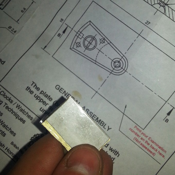
After roughly cutting out the shape I reapplied the image to check the progress. Here you can see it compared to the original technical drawing. I then trimmed the plate down further
After getting the right rough shape for the plate I used my centre punch to make the marks where I would need to drill holes. There would be four holes; one for the arbor, one for the screw and two for the steady pins
The marks from the centre punch can be clearly seen here. They are made so that the small drill bit will be guided towards the centre of the hole. This is an important step when drilling small holes as the drill bits are flexible and so have the tendency to “dance” over a surface until they start to cut
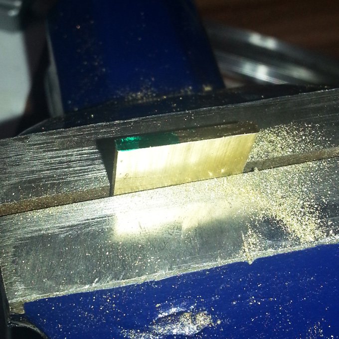
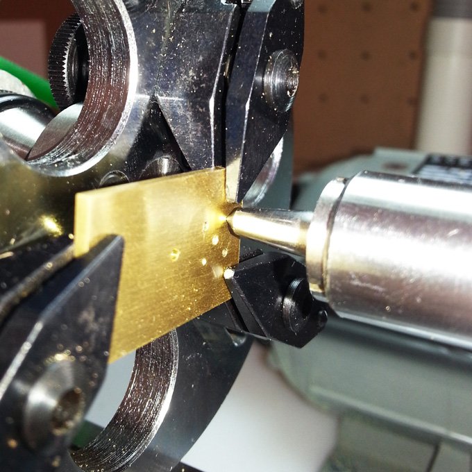
I secured the plate to the piece of brass that I would make the cock from. The idea was that this would enable me to get the holes all perfectly lined up. I held the brass in a self-centring 3 jaw chuck and used my milling attachment to line up the drill bit to the marks I had made in the plate
I only needed to drill two of the holes all the way through, as the holes for the steady pins only needed to be deep enough for the pins to fit partially into
The hole I had drilled was deliberately made too small. I used a broach to widen the hole to the correct diameter
However, when I tested the hole by putting a drill bit into the newly made hole it was immediately evident that the hole was not straight. I actually repeated this whole exercise 3 times and each time the hole I drilled was not perfectly straight. In the end I reasoned that although the milling attachment was steady, there was enough play in each of the adjustable parts that when combined this error was enough to be noticeable
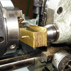
The plate had been super glued to the piece of brass the cock was to be made out of. To remove it I heated it under a flame. I could then clean off any remaining glue residue with a solvent
I realised that I was mostly just using the milling attachment because it was new to me; and as such it was exciting to try using something different. I also think I had overstated the importance of drilling the holes in the cock and plate at the same time. I reasoned that as long as I used the same scale image for both, then the holes should line up fine
So I put the plate in a mandrel and drilled the hole using a tail-stock (not the milling attachment that is pictured here). Then I simply had to move the plate in the mandrel to line it up with the drill bit. I did this by using a male centre in the tail stock and lining it up with the marks I’d made with the centre punch
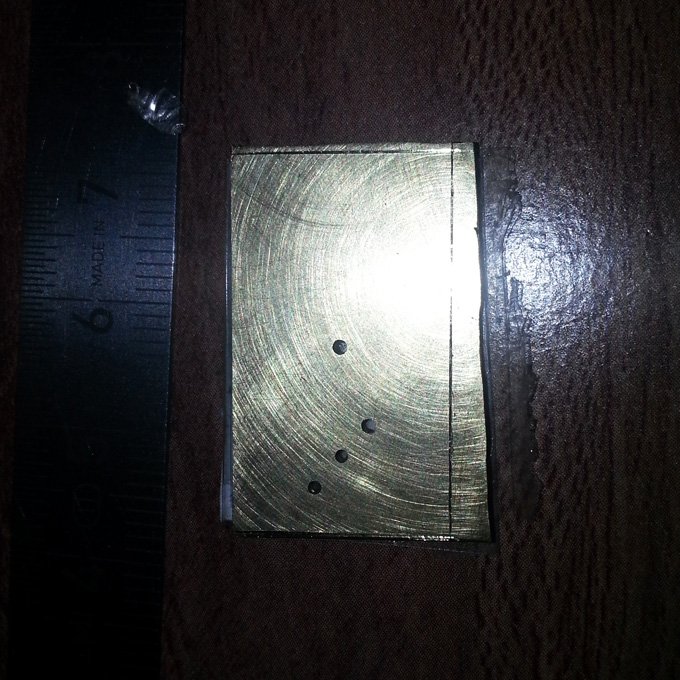
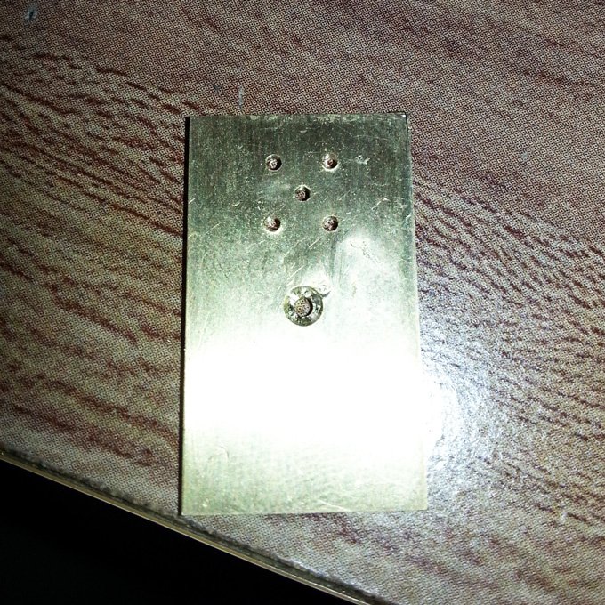
Throughout working I would always compare the piece to the original technical drawing. This gave me the confidence that I was on the right track and that everything looked like it should. Here I am checking that the drilled holes, especially the holes for the steady pins, look right
Another way to double check the drilled holes was to place a copy of the image back over the plate. I could then push a hole in the paper with a scriber and check where the hole was against the image
It was then time to finalise the shape of the plate. As you can see there was quite a bit of material still to remove
The quickest way was for me to use a piercing saw and make a horizontal cut
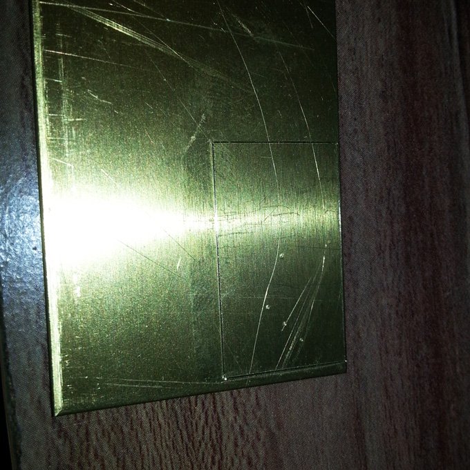
Once I had sawn the shape out, I could then flatten the sides with a file. It was at this stage that I made the first big mistake. I had started to make a saw cut to remove material from the length of the plate and upon double checking my measurements I realised that I had cut in too far. A simple, yet stupid mistake. You can see the cut at the top right of the plate
The answer was simple. I needed to start the plate again.
At this stage I only had around a day left to finish everything. Should I start again and spend another 3-4 hours to get to the same stage again, or do I just try and continue onwards?
With hindsight I should have started the plate again. But that is in the safe knowledge that I was able to finish everything; at the time I was working on this my biggest worry was that I wouldn’t be a position to submit anything at all.
So I tried to make the best of the situation. I reasoned that I would lose marks for the finish of the plate and possibly also the measurements. Maybe losing as much as 5-10% from the final mark.
Everything else seemed to be going fairly well up until this point and so I reasoned I could afford to take the hit.
To mitigate the visual effect of the cut, I hammered the brass as flat as I could in an effort to close the saw cut and then carried on with finishing it.
When filing the edges flat, I would constantly check the flatness with an engineer’s square and make sure the sides were all perpendicular to one another. The Vernier gauge was also very useful here, as you could use the jaws to ensure the sides were parallel while measuring it at the same time. When working on a side I would mark with a pen the places that were finished, slowly filling out the entire side with a pen mark as material was removed and the sides all became completely parallel to one another
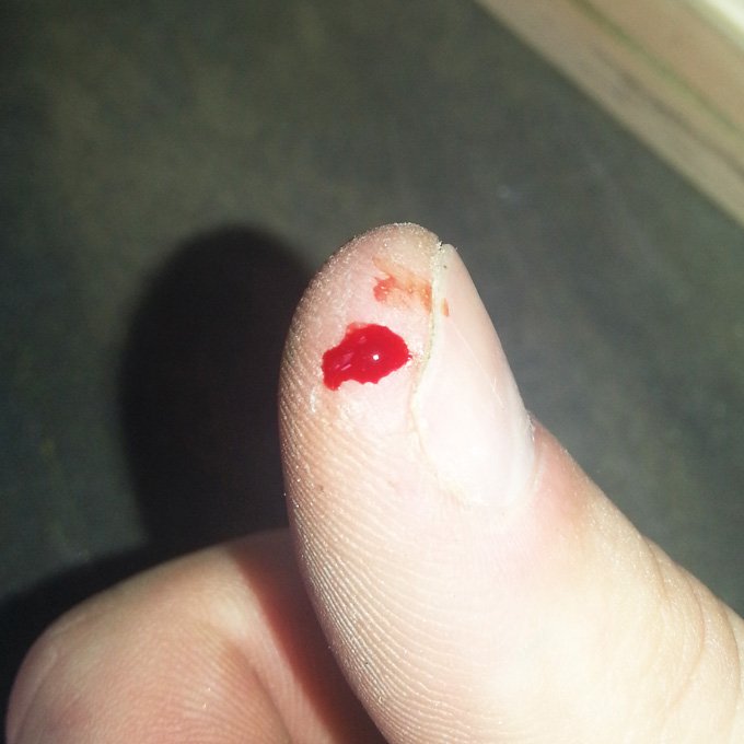
Once I had gotten all the sides flat and perpendicular I flattened the top and bottom of the plate too. I did this by rubbing the plate along some emery paper; starting with a coarse 400 grade paper, going to 800, 1200, 1600 and finishing with 2000. You only need to spend around 10-15 seconds on each grade of paper. The idea is that the 400 grade paper removes all the scratch marks, then the 800 grade removes the marks the rougher 400 paper leaves and so on. When you get to the extra fine grain of the 2000 grade paper you should be able to polish this out with diamond paste or something like Brasso
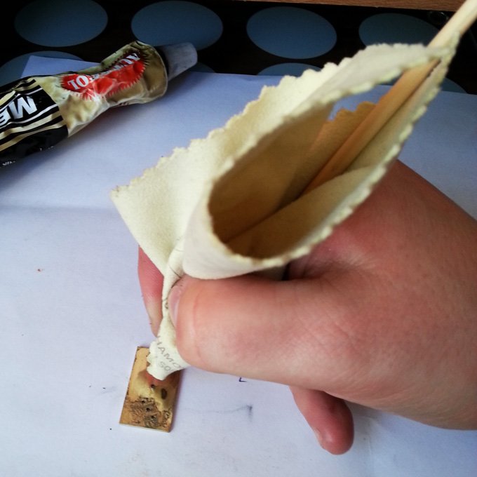
After rubbing the plate on the emery paper for a while I realised that it was not just the brass that was being abraded, but also the end of my thumb. Blood can quickly tarnish metal, so it’s a good idea to clean yourself up quickly. And it’s also probably a good idea to not sand your finger down!
I then glued the plate to a piece of scrap brass to avoid having to hold the plate directly. I then enlarged the holes to the correct diameter for both the pivot and the screw. The hole for the jewel was finished with a reamer. This is like a drill piece but with flat parallel sides. You choose a size that is marginally smaller than the jewel you are going to fit, so a 1.2mm jewel needs a 1.19mm reamer. This allows for a flush friction fit
Holding the piece in a vice I then used a tap to made the screw thread in the plate
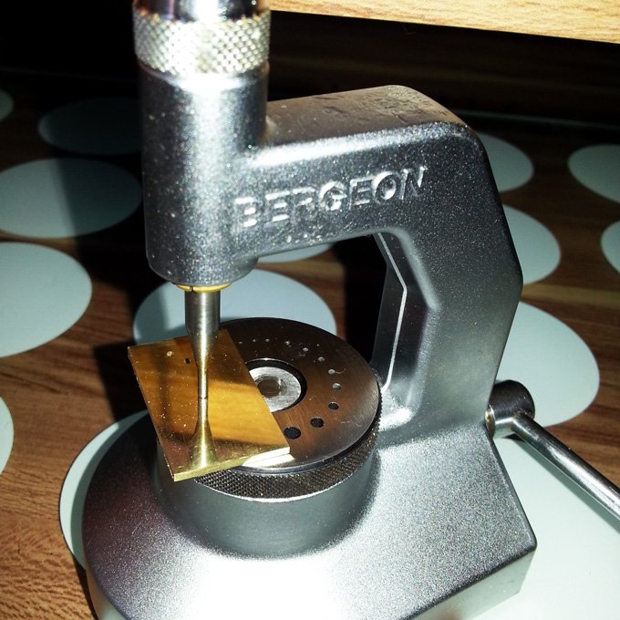
The next stage was to use a Rose Cutter to make the oil sink. This is done by turning the cutter on top of the hole, which will then remove material leaving a dish shape for the oil sink
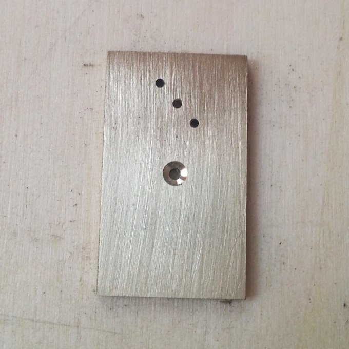
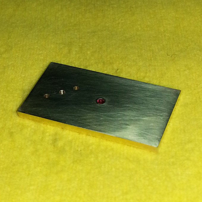
The finished oil sink. I had checked, and double checked and triple checked before I made the oil sink, but almost as soon as I had finished it, it became apparent I’d made a huge error
The steady pins holes I had drilled match up with the image above. The only problem is, that the oil sink should be on the bottom. I had drilled the holes in the wrong place, as I should have mirrored, rather than copied this image
I decided there were a few options available to me:
1) Remake the entire plate
2) Keep the plate as it is, flip it over and just have the have the holes for the steady pins on the wrong side
3) Completely drill out the hole for the arbor, including the oil sink. Then fit a bush in the hole and re-drill and make the oil sink on the correct side
4) Drill the holes again in the correct place and plug the incorrect holes
I didn’t feel I had enough time to rework the entire plate. I wish I did, and certainly would have done so if time wasn’t an issue, but I was in a position where I’d already made a mistake cutting it out, I’d now made another mistake drilling it, and so perhaps there was some comfort in the fact that a lot of the marks I would lose had actually already been lost.
I didn’t want to keep the plate as it was. This solution would have been the best use of my time, but I just couldn’t bring myself to leave such an obvious mistake.
So I seriously considered my 3rd and 4th options. In the end, the 4th choice won out, primarily because of the size of the correction needed, and also that the steady pins were actually covered up by the balance cock. It wasn’t going to be a focal point of the piece, whereas the hole for the jewel would be.
So I marked the correct places for the holes, and made a mark with the centre punch. Here I am lining up the lathe with a male centre to ensure it’s in the correct place before replacing the centre with a drill and making the hole
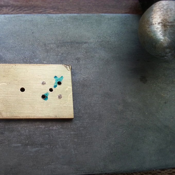
The finished holes. 2 wrong. 2 right
I took a permanent marker and marked the correct holes on both sides. I was paranoid that I’d actually end up plugging the holes I’d just drilled, so this helped me act in confidence. I then turn two small brass cylinders the diameter of the holes and pushed them into place. I then carefully shaped the ends of the plugs on both sides with the ball end of my hammer, so that they were flattened to be wider than the drilled holes
There was a worry that the vibration from the hammering would cause the little flap of brass that remained in the corner (from my earlier cutting mistake) to come loose. So I added some superglue to it while I hammered, which could be easily removed later. I then was able to tap away at the plugs until they became flat and I was confident that the holes had been completely filled
Carefully I then reworked the plate on the emery paper as I had done before until the rivets disappeared. They were still visible if you looked for them, but overall I was happy with how everything had turned out
Once the jewel was added I wouldn’t be able to polish the plate flat. One of the big downsides of working with a rivet, is that I was worried about them showing through so much that I didn’t flatten the plate as well as I could have done. You can see from the above image that all the corners are a little rounded. To polish the piece I used different grades of lapping paper glued to a piece of peg wood. Lapping paper comes in different colours depending on the grade; if I remember rightly it’s Yellow, Blue, Pink then Green. I used it on peg wood so that I could localise the area I was working on, and also avoid rounding the edges of the plate
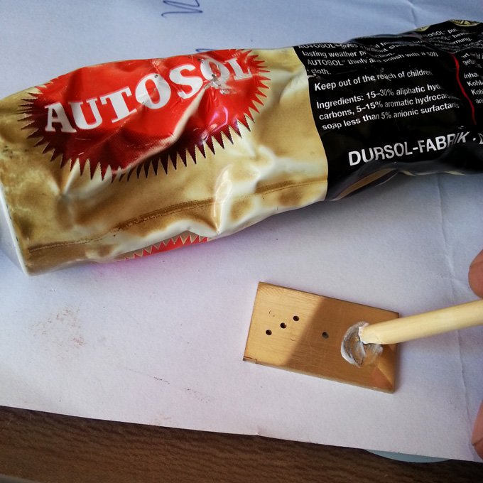
For the final polish on brass I used some Autosol rubbed in with some peg wood. You can see the edges of the rivets I had made quite clearly here, but that is mostly because they have the discoloured polish around them
To then buff the polish up I wrapped my peg wood in some Selvyt. As before this helped me localise my polishing and avoid rounding the edges of the plate
Once polished I just had to push the jewel in. I am using a centre punch here. I should be using a jewelling set, but they cost a fortune, and other than this one task I didn’t have a need for one. I lightly tapped the punch until the jewel was flush to the plate
The finished top of the plate. You can see the sawing cut mistake on the bottom left, but it wasn’t too noticeable. The two rivets I’d made were pretty clean, and for the most part were only visible because the brass was a slightly brighter colour than that of the plate
The finished bottom of the plate, with the oil sink on the correct side! I gave the bottom a straight grain finish as we had been requested, by rubbing it in one direction on some 400 grade emery paper
Hi Colin, great article and as I’m reading, I’m reliving the exam, you certainly know how to put
Yourself under pressure! can’t wait to see your approach to the Cock.
I made the Plate twice, the Arbor twice, made two blued screws – keeping the best for the finished piece, the other to assist in assembly/spotting holes, would liked to have made the Cock again but had invested too much time in it, and concluded as you did that I would have to take a few hits on available marks, I also managed to lose a Jewel
Colin interested to know if you’re doing Certificate or Diploma?.
Great website, keep up the good work
Regards
Peter


Peter Currie
26 April, 2014 at 11:57 pm
Hi Colin, great article and as I’m reading, I’m reliving the exam, you certainly know how to put
Yourself under pressure! can’t wait to see your approach to the Cock.
I made the Plate twice, the Arbor twice, made two blued screws – keeping the best for the finished piece, the other to assist in assembly/spotting holes, would liked to have made the Cock again but had invested too much time in it, and concluded as you did that I would have to take a few hits on available marks, I also managed to lose a Jewel
Colin interested to know if you’re doing Certificate or Diploma?.
Great website, keep up the good work
Regards
Peter
Colin
28 April, 2014 at 6:32 am
Many thanks for your comments Peter.
I hope the memories weren’t too painful!
I’m currently doing the Diploma, I started on the exams in the first year it was introduced